This time we’re diving into the basics of parametric CAD design and laser cutting. The parametric design will be a foundational sketch for a small laser cut model made of wood. This model will also feature engravings as both excercise and visual effect.
For this excercise I decided to create a simple geometric model of a fox, which will be “textured” using different engravings. The final result can be found here1.
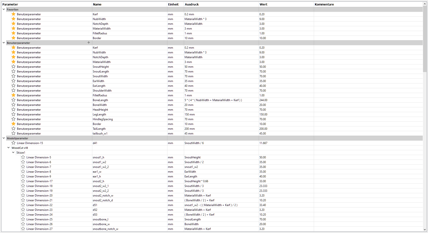
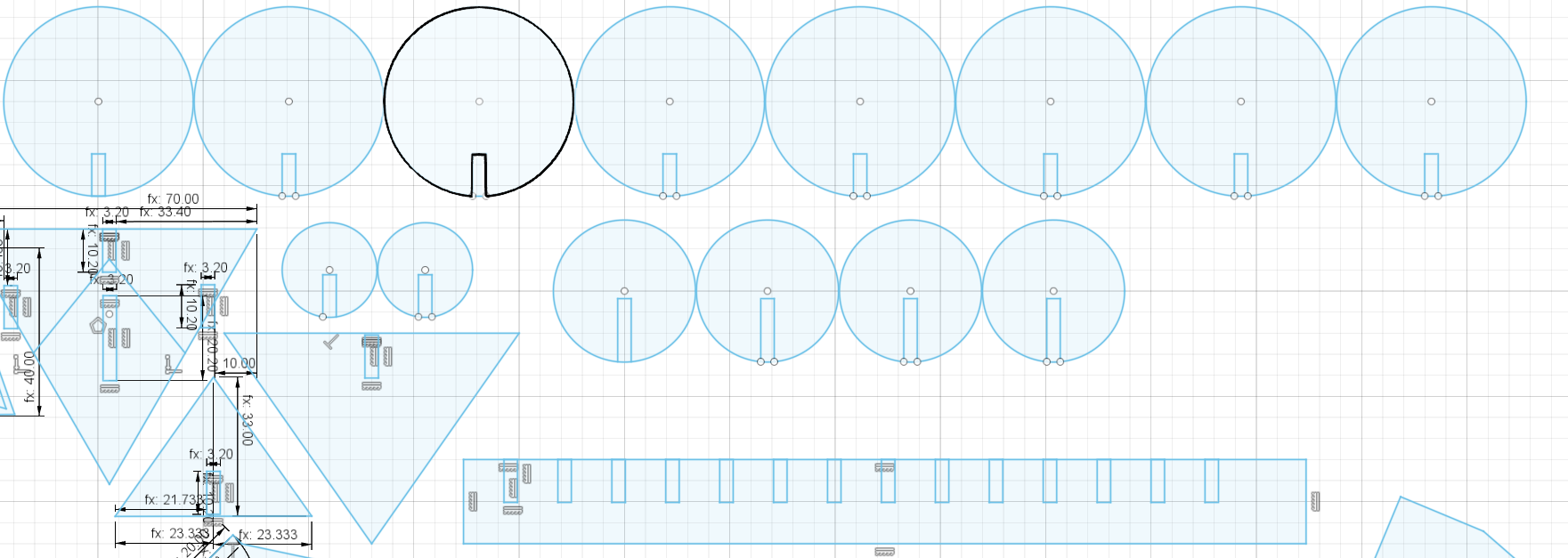
Due to it’s three-dimensional, joint-based approach our model will be fairly complex, thus I will try to simplify explaining some of the components’ designs as the main focus lies on how parametric design automates and structures it. Just as a primer, you can see the final spreadsheet down below:
Also keep in mind that not all decisions in a parametric design can be entirely automated. Depending on the type of material used, manual adjustments need to be made. For design purposes I assumed the following:
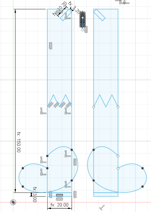
Let’s start off with something rather simple, then. Below you can see the fox’ face plate and ears. The square shapes at the top of the head as well as the bottom of the ears serve as joints and have been measured MaterialThickness+Kerf for each side, with parallel constraints to ensure clean and consistent insertion despite odd angles. All the other inner shapes have been defined to serve as reference points for engravings later on:
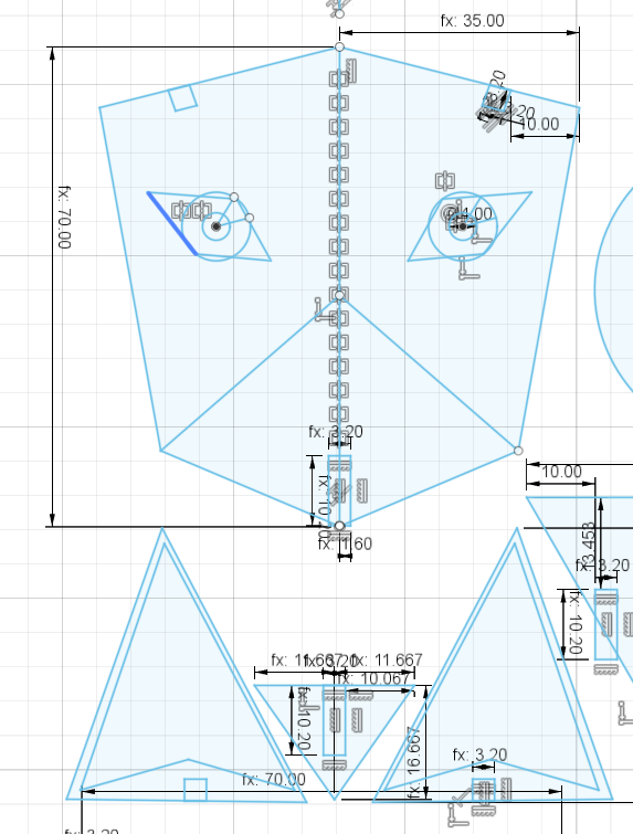
As fox faces are not flat of course, below you can see the snout, which has been designed with a length of about 7cm in mind.
Below the ears we encounter the first of what I refer to as bones. These are little helper pieces which are supposed to serve complex joints between similarly orientated cuts, since the suspected 3mm wood we’re about to use for assembly is unable to safely bend without use of complex patterns.
For assembly all three snout pieces as well as the face plate are meant to be mounted on the aforementioned snout bone. The sole down-facing notch to the right will serve mounting the face to the rest of the body, as will soon be explained.
Designing the torso turned out a tricky as precise measurements were needed across various angled joints to ensure a stable resting position of the torso and feet.
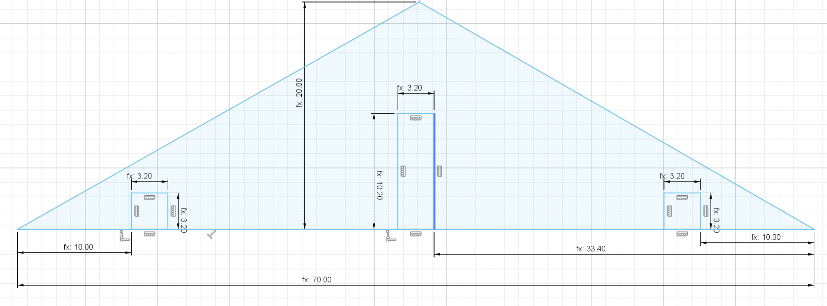
To connect head and front feet to the torso, I created a shoulder bone with 4 joints:
(MaterialWidth+Kerf)×((BoneWidth/2)+Kerf). The legs have been adjusted to fit in a 45deg angle with the shoulder bone(MaterialWidth+Kerf)^2^(MaterialWidth+Kerf)×((BoneWidth/2)+Kerf)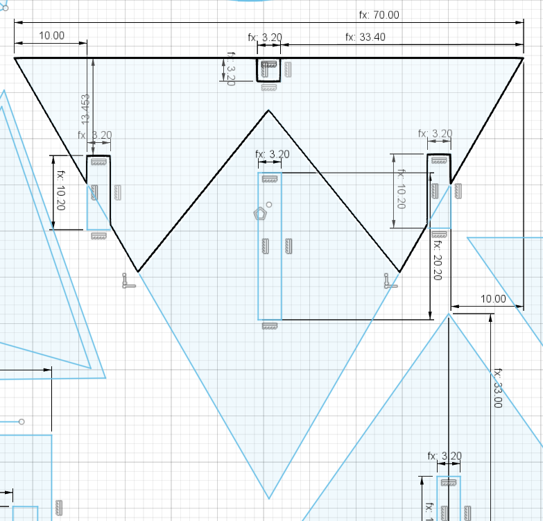
The front legs I created using some rectangles and a spline. At the top you can see the aforementioned shoulderbone connection and at the bottom you can see connection joints for a set of stands that I decided to create for better standing. For the legs’ thickness I used the regular bone thickness just in case of necessary adjustments:
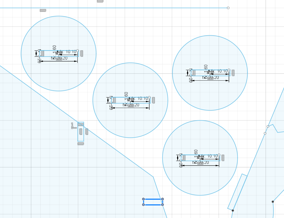
For stable standing I also created four standing plates for the feet to fit into. They are of 20mm radius with a slot in the middle of (MaterialWidth+Kerf)×((BoneWidth/2)+Kerf). :
Designing the Legs turned out to be a mostly non-parametric procedure, as the complex shape only served aesthetics, aside from a few necessary joints.
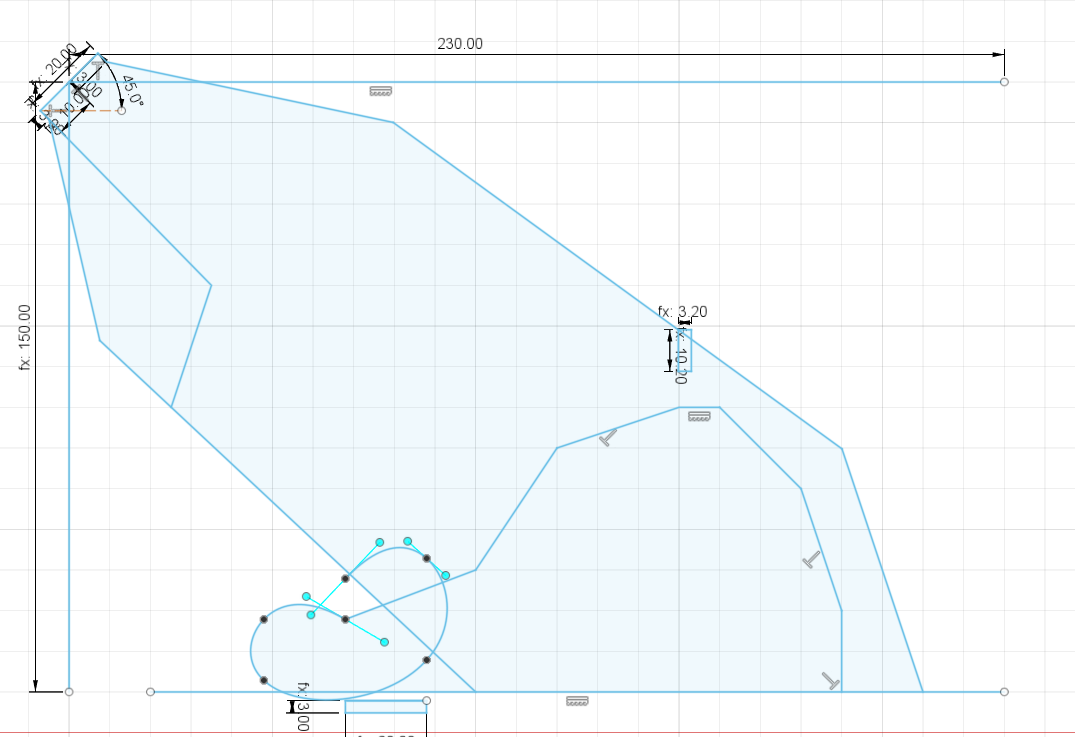
Below you can see the hip bone, which has been used to connect the two hindleg pieces to the main torso:
For the tail I designed a tail bone (visible at the bottom of the image below) which would stick perpendicular into the fox’ back with circles of 3 sizes stuck onto it, suggesting volume.
The gaps have been defined through a rectangular pattern on the bone and snapping with defined distance between the circle’s midpoint and one of the gap’s corners for centering in case of the “bushes”. The gaps’ size has been defined using standard proportions (MaterialWidth, Kerf and BoneWidth/2):
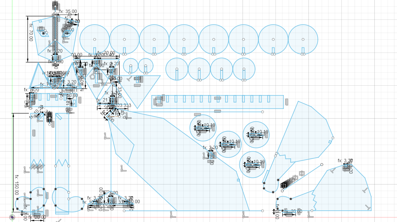
Below you can see the final sketch, which I exported into the industry-standard (non-parametric) Autodesk DXF format for use in Rhinoceros (the laser cutting system used in this excercise). The DXF export is also available for download2:
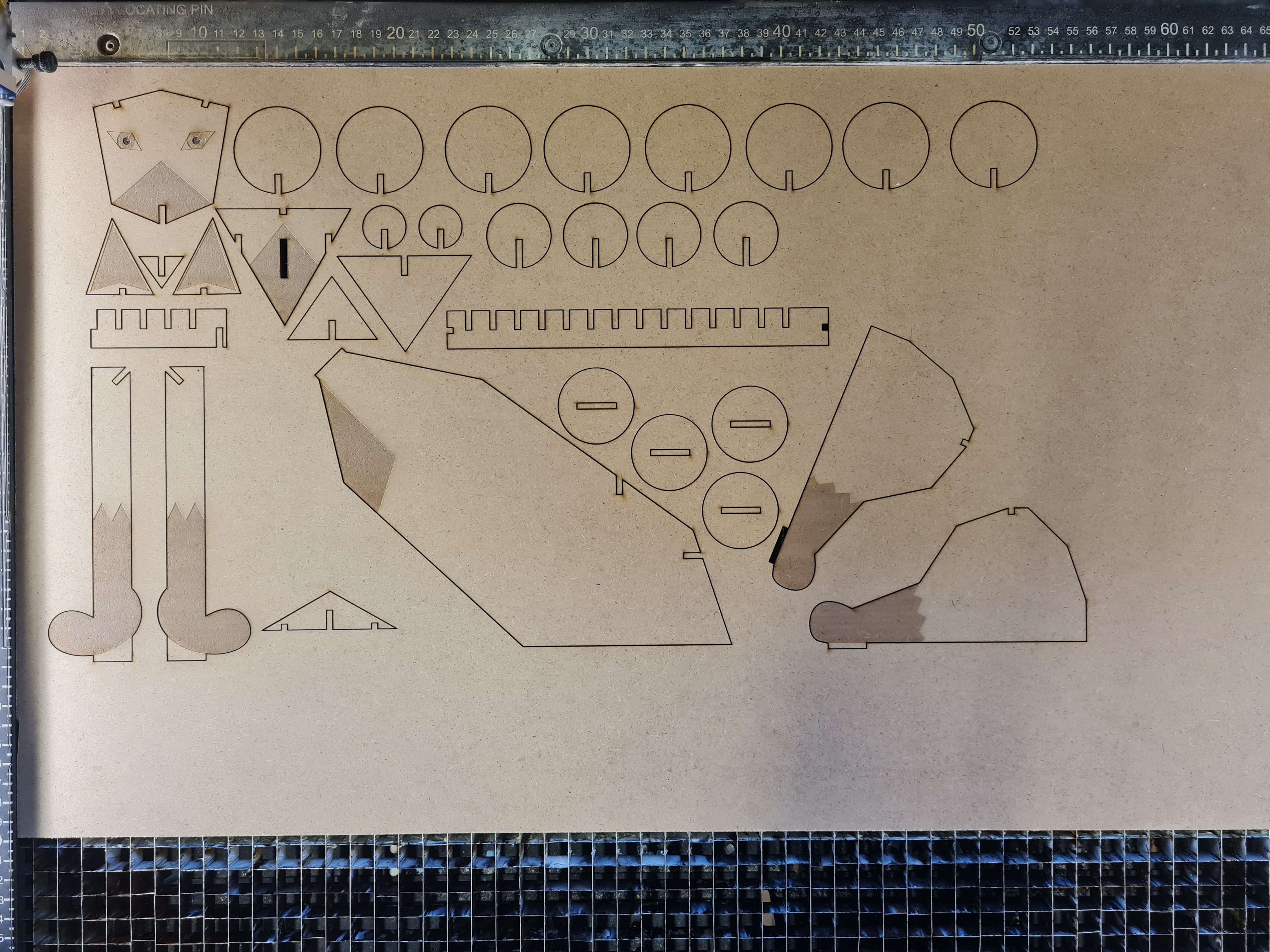
Much like expected I was able to use 3mm wood to turn my laser cut into reality.
However, after doing a test cut, I started to notice a problem with the Kerf:
The Kerf is a measurement that is used to describe the amount of material a cutter removes from the used resource in order to cut it.
Although my estimate of 0.2mm Kerf was reasonable, I accidentally applied it to to increase the width of the joint holes, resulting in a loose cut that could easily fall apart.
Even worse was that my design has grown so complex over time that turning the kerf into a negative value for the final version wasn’t possible due to calculation issues, something that could’ve been an easy fix.
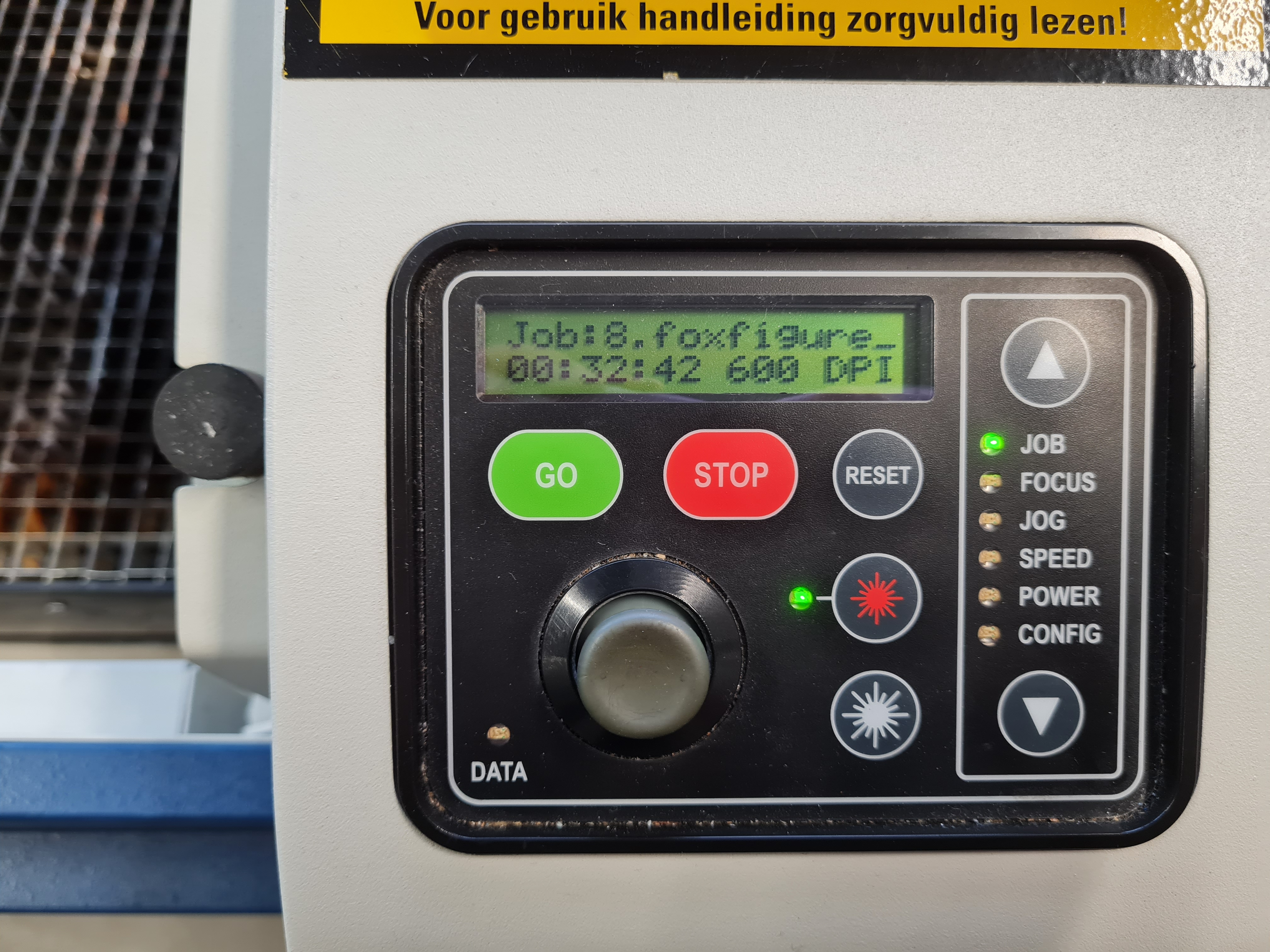
After defining all necessary parameters in Rhinoceros (parameters listed below), the final cutting job ended up taking about 33 minutes, mostly due to the legs’ engravings being spaced quite far apart. Thus I recommend anyone doing laser cutting with engravings to closely clump together engraving areas by type to speed up the process.
| Attribute | Laser power | Laser speed |
|---|---|---|
| Dark engravings | 100% | 75% |
| Light engravings | 25% | 75% |
| Markings | 30% | 80% |
| Cuts | 100% | 5% |
In the image below you can also see some oversights on my part: First, one leg is missing the nub necessary to join it to one of the circular foot pieces. The tail’s bush pieces were also mistakenly measured according to the bone width, while the desired effect required measurement of half the pieces’ length in order to center them. Lastly, the pelvis bone was measured too short such that the hindlegs cannot be fit onto them. Some components of the model, as well as the test cut (white) can be seen below:
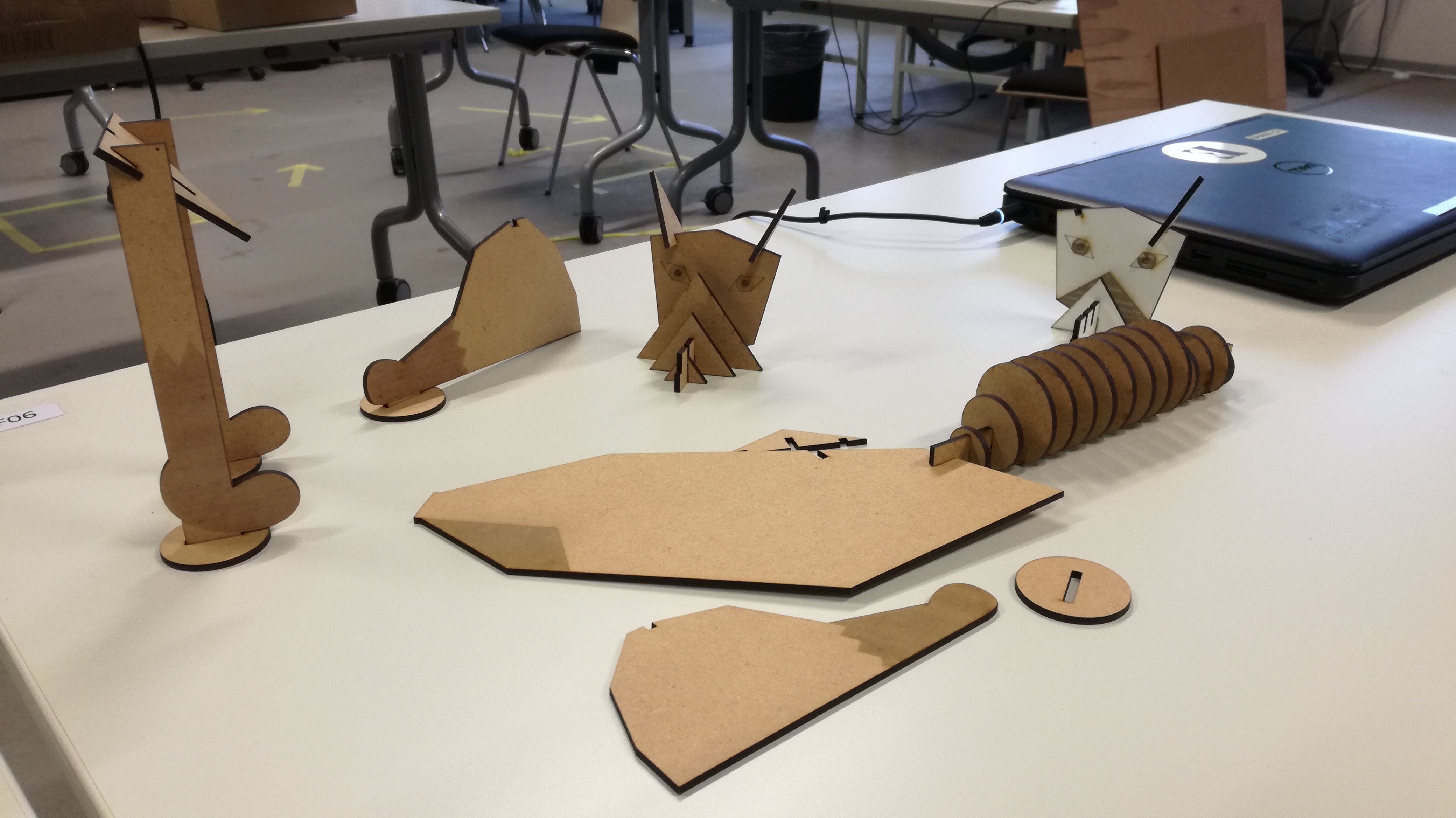
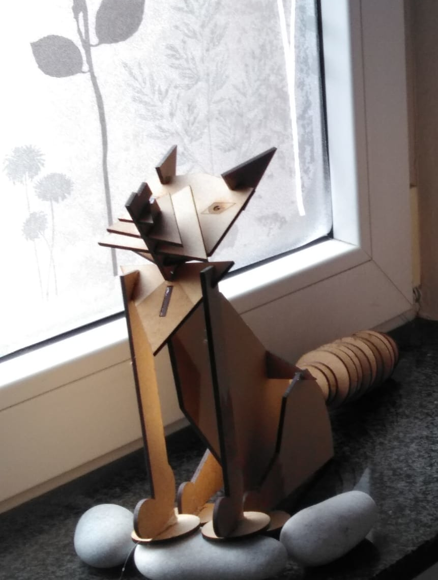
Following makeshift assembly using glue to fixate the joints, as well as doing some correctional cutting using a good old saw, you can see the final result below